The main benefit of the pressure decay method is the optimal ratio between price and performance. In fact, it is possible to achieve a good measurement resolution, down to 0.1 cc/min, at the cost of few components: typically, the leak-test instrument and the fixture to seal the part under test. In many cases, the fixture is just a single pipe that connects the leak-test instrument to the part.
The differential pressure decay leak test can provide a higher sensitive measurement for many applications. The sensitivity of the transducer is independent of the actual pressure, in absolute terms, so that the highest accuracy can be achieved even at a high test pressure.
The most common leak test methods can determine the value of the leak (typically measured in cc/min or mbar/sec) by using:
- Pressure decay (with or without reference volume)
- Flow inspection (for big volumes)
- Tracer gas inspection (high performances)
Some technologies are able to identify the position and the value of the leak using methods such as:
- Air bubble (under water inspection)
- Tracer gas (using sniffing probes)
The pressure decay method is the most common and cost-effective leak inspection technology used to test a wide variety of parts. These parts can range from the automotive components like cylinder blocks, cylinder heads, and gear boxes to bio-medical components. The gas used is common compressed at a pressure from vacuum to 10 bar (sometimes higher). The supply of clean and dry air is recommended to limit the influence of any thermodynamic effects.
In the pressure decay method, the part under test is sealed and filled with air or is put into a chamber where a vacuum is created. If the part has a leak, the pressure inside the component will change. The pressure variation per unit of time between the reference volume and the volume under test is measured by a relative pressure transducer.
A more sophisticated version of this method is the differential pressure decay. In a differential pressure decay test, the pressure drop is measured inside the part. This is then compared to the pressure inside a reference volume, filled at the same pressure as the part.
A leak-tester is a specific electronic unit providing a suitable pneumatic circuit and all the necessary elaborations.
The practical applications of this leak testing technique are very frequent. However, two important conditions need to be met:
- The volume of the part must be known and not variable X in most mechanical parts).
- The leak being measured is not so big that the pressure decay system cannot maintain a constant test pressure, ultimately distorting the leak calculation.
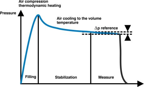
The diagram below shows a typical pressure decay measuring cycle where the pressure inside the part being tested is represented over the time axis.
At the beginning of the cycle, the volume under test is pressurized with air at the desired level. Then a stabilization time is necessary to let any thermodynamic effects and air turbulence run out. Finally, a transducer reads the variation of pressure for a few seconds to allow the calculation of the amount of leak.

Examples of applications according to market segments:
- Automotive: leak test of oil/water/fuel circuits in the car or truck engines and battery packs, car-lights, fuel system manifolds, oil pumps, gear boxes, brake system, filters, etc.
- Medical: blood bags, etc.
- Pneumatic: compressors, cylinders, filters, vacuum components, etc.
- Oleodynamic (Hydraulic): pumps and distributors, filters, force transmission boxes, etc.
- Heating: burners, heaters, radiators...

